

 Français


Open Hardware


- Fully compatible with interface extensions.
- Address can be modified through I2C and communication.
- It can connect 2 steering gear and output PWM drive directly.
- Up to 4 bi-directional DC motors
- Up to 2 stepper motors (unipolar or bipolar)
- 4 H-Bridges: TB6612 chipset provides 1.2A per bridge (3A for brief 20ms peaks) with thermal shutdown protection, internal kickback protection diodes. Can run motors on 4.5VDC to 13.5VDC
- 2 connections for 5V 'hobby' servos connected to the Arduino's high-resolution dedicated timer - no jitter!
- Big terminal block connectors to easily hook up wires (18-26AWG) and power
- Tested compatible with Arduino UNO, Leonardo, ADK/Mega R3, Diecimila & Duemilanove. Works with Due with 3.3v logic jumper. Works with Mega/ADK R2 and earlier with 2 wire jumpers

- 16x2 LCD & keypad shield for
- Utilizes the extremely common HD44780 parallel interface chipset
- Interface code is freely available
- uses 4 Bit For Arduino LCD Library
- Blue Backlight with white words (screen contrast adjustment)
- Reset button
- Its Up, Down, Left, Right buttons use only one analog input
- Size:8cm x 5.9cm - 3.15inch x 2.32inch

- Material:CNC Aluminium
- Length:35mm
- Color: blue
- Adjustable type servo arm
- 25T Spine for Futaba JR TP HD Servos
- Compatible with MG995 and MG996R

- Examples of uses (lien)
- Module schematic (jpg)
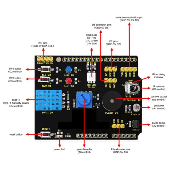
- Arduino compatible
- 2 push-button
- 2 Led (red and blue)
- 1 Led RGB
- 1 IR receiver
- 1 Brightness sensor module
- 1 LM35D temperature sensor module
- 1 Passive buzzer module
- 1 Rotary potentiometer module
- 1 DHT11 temperature and humidity sensor module
- 1 I2C interface (A4 SDA, A5 SCL)
- 1 TTL serial port
- 2 channel digital ports (D7, D8)
- 1 channel analog port (A3)
- 1 Reset button


The multifunction shield features some most useful electronics divided into segments:
- Four LEDs
- Three pushbuttons
- A reset button
- A piezo-buzzer
- An LED display module (four-digit, seven-segment)
- Two serial LED display driver ICs(74HC595)
- A multi-turn trimpot (10K)
- A port for DS18B20 temperature sensor
- A port for TSOP1838 infrared receiver module
- A APC220 wireless module interface (serial/UART interface)

- NRF24L01+ 2.4GHz Antenna Wireless Transceiver Module
- Maximum operating speeds up to 2Mbps, GFSK modulation efficiency, Anti-interference ability, particularly suitable for industrial control applications
- 125 Channels, Multi-point communication and frequency hopping to meet the communication needs
- Built-in hardware CRC error detection, Multipoint communication address control
- Low-power 1.9 ~ 3.6V, only 1uA on Power down mode
- Arduino and Raspberry Pi compatible
- Datasheet (PDF)
- Schematic (PNG)

The ESP-01S ESP8266 WiFi Module is a self contained SOC with integrated TCP/IP protocol stack that can give any microcontroller access to your WiFi network. The ESP8266 is capable of either hosting an application or offloading all Wi-Fi networking functions from another application processor. Each ESP-01S ESP8266 module comes pre-programmed with an AT command set firmware, meaning, you can simply hook this up to your Arduino device and get about as much WiFi-ability as a WiFi Shield offers (and that’s just out of the box)! The ESP-01S ESP8266 module is an extremely cost effective board with a huge, and ever growing, community.
This module has a powerful enough on-board processing and storage capability that allows it to be integrated with the sensors and other application specific devices through its GPIOs with minimal development up-front and minimal loading during runtime. Its high degree of on-chip integration allows for minimal external circuitry, including the front-end module, is designed to occupy minimal PCB area. The ESP8266 supports APSD for VoIP applications and Bluetooth co-existance interfaces, it contains a self-calibrated RF allowing it to work under all operating conditions, and requires no external RF parts.
Features:
- 802.11 b/g/n
- Wi-Fi Direct (P2P), soft-AP
- Integrated TCP/IP protocol stack
- Integrated TR switch, balun, LNA, power amplifier and matching network
- Integrated PLLs, regulators, DCXO and power management units
- +19.5dBm output power in 802.11b mode
- Power down leakage current of <10uA
- 1MB Flash Memory
- Integrated low power 32-bit CPU could be used as application processor
- SDIO 1.1 / 2.0, SPI, UART
- STBC, 1×1 MIMO, 2×1 MIMO
- A-MPDU & A-MSDU aggregation & 0.4ms guard interval
- Wake up and transmit packets in < 2ms
- Standby power consumption of < 1.0mW (DTIM3)
Documents:
- NURDspace Wiki (Schematic, Datasheet, & More!)
- Instructables Tutorial
- ESP8266 Community Forum
- AT Command Set
- GitHub (ESP8266)
- GitHub (GCC-Xtensa)
- Graphical Datasheet


- Input voltage : 3.2 to 40 Vdc
- Driver : L298N (Dual H Bridge)
- Power-supply: 5V à 35V
- Peak current : 2A
- Size: 3.4cm x 4.3cm x 2.7cm
- On-board 5V reulated output supply

- Standard 16x2 character LCD display
- Supply Voltage: 5V
- It has a basic 16 character by 2 line display with a blue background with white characters
- 5 x 8 Dots With Cursor
- Use HD44780 controller (datasheet)
- Include a 1x16 unsoldered male header (soldered available in options)

- TB6612FNG Datasheet (PDF)
- Schematic (PDF)
- Adopted ceramic capacitor, it has a more stable performance
- The TB6612FNG motor driver can control up to two DC motors at a constant current of 1.2A (3.2A peak)
- Built-in thermal shutdown circuit and low voltage detecting circuit
- CW/ CCW/ short brake/ stop motor control modes

- High sensitivity sound detection module with 2 Outputs (1 analog and 1 digital)
- Voltage: 3.3 to 5 VDC
- Frequency response: 50 Hz - 20 KHz
- Sensitivity: 48 - 66 dB
| Voltage | 3.3Vdc to 5Vdc |
| Frequency response | 50 HZ to 20Khz |
| Impedance | 2.2Kohms |
| Sensitivity | 48 to 66 dB |
| Dimensions | 44 x 15 x 10 mm |

- 2*5V servo motor (servo) port is coupled to its high-resolution high-precision timer - no jitter
- Up to four bi-directional DC motor and 4 PWM speed (about 0.5% resolution)
- Up to 2 stepper motor control, single / double-step control, staggered or micro-step and the rotation angle control
- 4-channel H-bridge: L293D each bridge chip provides .0.6 A (peak 1.2A) current and with thermal shutdown protection, 4.5V to 36V
- Large terminal terminals make wiring easier (10 - 22AWG) and power supply

- Micro-USB connector
- Input : 7 to 12 V
- Output : 3.3V and/or 5V
- Easy selection of voltage output
- Compatible with MB102 breadbord

- LCD display 16x2 white fonts on blue background
- Serial communication : IIC/I2C/TWI
- I2C address 0x4E
- Arduino IDE compatible
- Schematic (PNG)

- BMP180 Datasheet (PDF)
- Module (GY68) schematic (JPG)
- BMP180 you can achieve accuracy of 1m,
- resolution: Up to 0.03hPa / 0.25m, Operating voltage: 3 to 5VDC
- Pressure sensing range: 300-1100 hPa (9000m to -500m above sea level)
- -40 to +85°C operational range, +-2°C temperature accuracy This board/chip uses I2C 7-bit address 0x77.
- Module size: 13 mm x 10mm x 2.7mm

- Module schematic (JPG)
- Module Working Voltage: 4.5-5.5V
- Launch Tube Pressure Drop: Vf=1.6V
- Launch Tube Current: If<20mA
- Signal output: A, B two lines; TT power level;
- Resolution: 0.01mm
- Measurement frequency: 100KHz
- Disc diameter: 24mm
- Inner Disc Diameter: 4mm
- Encoder resolution: 20 lines
- Speed measuring sensor configuration: measure line 1 motor speed
- Application: For experiment